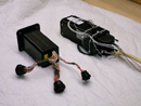
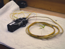
| These first two pictures look like the same picture. I think one is a little less blurry. Other than the connector for down loading the sampled data (included on a JPI) and the wires for the temperature probes, there is only power and ground on a JPI. This one has 3 additional wires for fuel flow. |
|
| The point here is that the JPI (on the right) has 3 "D" shapped connectors whereas the EI has 3 round "cannon plug" type connectors. The JPI in these photos is set up for fuel flow. For this plane, I wire tied the connector to the side of the unit. |
|
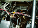
| In this picture, I'm looking up at the bundle of wires which goes to the probes on the EI system. It's quite a massive bundle of wires. You can't see in this photo, but, there are a bunch of heavy gauge wires for lighting and all sorts of stuff on the EI. You can just see the cannon plugs. |
|
| Another shot from the bottom showing more of the temperature probe wires all bundled together under the panel. Since you can't cut these to shorten them, you need to do something with them. |
|
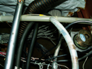
| Here is the left side of the plane showing where the EI wires originally came out of the fire wall. Initally, I tried to straighten them just to see if they could be made to look nice and neat. Can't be done. Too big and bulky. |
|
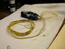
| Here are a couple of shots of the JPI 700 with all of the wires needed for installation. They can all be cut to fit. |
|
| Another view from the left rear. . |
|
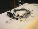
| Contrat those with this bundle of wires on an EI system. The shielded wires are very stiff and a real pain-in-the-ass to work with. This is the EI I took out of Suann's Tiger. I replaced it with a JPI 700. |
|
| Another picture of the wires on a JPI. What can I say? It's functional. So is a PC. |
|
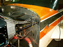
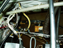
| OK, here we are, looking back up into the same area previously occupied by the EI bundle of wires. This is the JPI installed. Do you see the bundle of yellow wires? That's it. The three wires for the fuel flow are also in that bundle; as are wires for oil temperature, carb temperature and outside air temperature (OAT). I left some slack in the wires. |
|
| Here is what it looks like from the outside (from the right side). I used the hole in the firewall where the tach cable comes out. Really, why drill another hole in the firewall? With an EI you need to drill a big hole just to get that mass of wires through. |
|
| Here is a shot from above. At this point, I use the existing wire mounts for the aircraft wires (which go to the battery and starter relays, B+ to the main buss, and wires for things like map and cabin lights and the landing light.) and make the whole JPI install snug against the firewall. From the area of the relays, I follow the wires up to the area of the lower right engine mount and then branch off to the respective locations. Wires to the left side go along the bottom of the accessory housing toward the lower left engine mount. The exhaust risers are rotated 180 degrees so the EGT probes are hidden under the engine. Now you know all the secrets. |
|